Synopsis
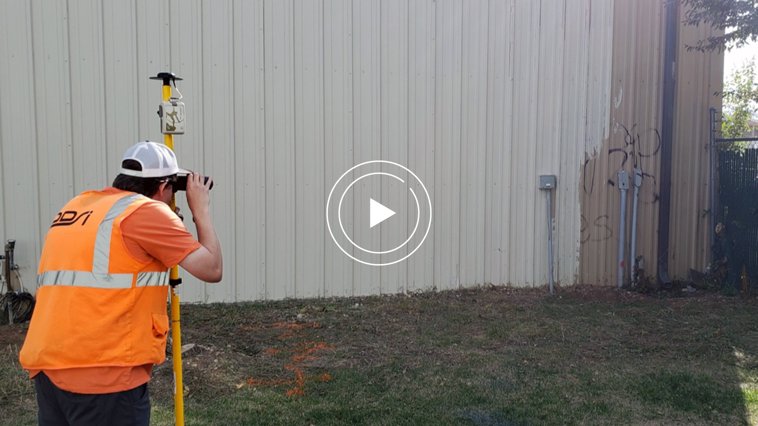
In this Esri AEC webinar, Esri director of AEC Marc Goldman hosts a group of GNSS and GIS professionals to explain the benefits of laser mapping technology. Doug Morgenthaler, a product engineer group lead at Esri, first explains the capabilities of field data collection app ArcGIS Collector. Sarah Alban, marketing director at Eos Positioning Systems, then goes over the advantages and capabilities of the Eos Laser Mapping Solution with ArcGIS Collector. Finally, Mike George, GIS director and project manager at DDSI Global, ends the webinar by reviewing the workflows of Eos Laser Mapping and the successes it has brought to his consultancy.
Click play to watch the webinar recording, or keep scrolling to read the transcript.
About Esri


MARC GOLDMAN: Hello everyone. Welcome, and thank you for joining today’s webinar titled, ‘Capturing Hard-to-reach Assets with Decimeter Accuracy.’ My name is Marc Goldman. I’m the director of architecture, engineering and construction industry solutions at Esri and I will be your facilitator for today’s program.
Esri is the largest location intelligence and digital mapping technology company in the world. Our solutions help architects, engineers, general and specialty contractors, bring a geographic context to the engineering and design projects they’re working on. We ensure access to the most up-to-date data by all stakeholders across all stages of projects and of all sizes and complexity. Through our location intelligent solutions, we’re providing context and geo-enabling AEC firms. We’re helping firms devise improved workflows, allowing them to build smart communities and assets for the future.
Introductions: Capturing Hard-to-reach Assets with Decimeter Accuracy
Today’s topic, ‘Capturing Hard-to-reach Assets with Decimeter Accuracy,’ is one that I find very interesting. As an AEC professional, over the years I’ve worked in architecture, I’ve worked in engineering, I’ve worked in construction and facilities management. But I’ve never worked in the field as a surveyor, I’ve never had to contend with the complexity of documenting existing conditions in challenging situations. So any opportunity to better understand how other AEC participants get their work done efficiently and accurately, I’m eager to be part of it.
With that, let me introduce our team. Joining us today are Doug Morgenthaler with Esri, Sarah Alban with Eos Positioning Systems, and Mike George with DDSI Global.
Doug Morgenthaler is a product engineer group lead at Esri, he’s the product owner of ArcGIS Collector.
Our second presenter after Doug will be Sarah Alban, and she’s the head of marketing for Eos Positioning Systems. She formerly worked at Esri and at National Geographic.
Our third presenter will be Mike George. A little about Mike George, he is the GIS director and project manager at DDSI Global. DDSI provides geomatic services to the oil and gas, the telecom, and local government sectors. Mike is also a licensed UAV pilot.
So with that, I’ll go ahead and turn it over to you Doug.
About ArcGIS Collector
DOUG MORGENTHALER: Thanks, Mark.
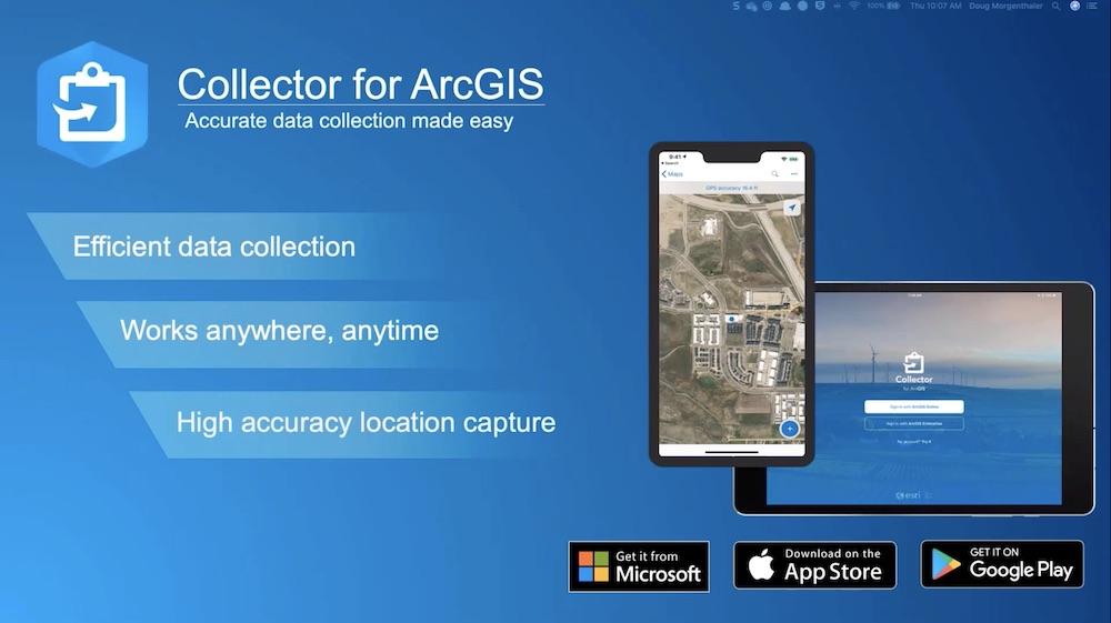
So I wanted to talk to you for a few minutes about ArcGIS Collector. Collector is our premier field data collection tool. Collector uses a configurable mobile app that supports a wide variety of workflows and industries. It supports two primary workflows; capturing new assets, or visiting or inspecting existing assets or observations.
Little or no internet connectivity is still, unfortunately, a reality from many of our data collection projects. Collector has a strong support for occasionally connected or fully disconnected workflows to ensure that you can complete your work anywhere or anytime.
How Collector supports AEC
High accuracy is a key capability for many AEC workflows. We support a wide variety of GPS receivers, including the Eos Arrow line of GNSS receivers. We do support a wide variety of correction sources that may be using RTK or satellite-based corrections to achieve up to centimeter accuracy in real-time, no post-processing required.
We also support additional capabilities to collect more accurate information for more specific workflows, one of those we’ll be talking about today. What we’ve seen is that Collector over the past few years has started to be used in more workflows where you may have traditionally seen those being done by traditional surveyors.
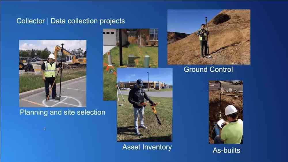
So this just highlights a number of different aspects where we see Collector being used today for common engineering and construction workflows such as site planning, ground control for aerial imagery collection and geo-referencing using UAVs or UAS, consolidating design decisions before construction begins, or accurately capturing as-built assets once construction is underway or it’s been completed. Collector allows you to engage your field workflows to capture this information to achieve the spatial accuracy that you require for your particular project. So, Collector is just a part of our larger field operations suite.
Field operations apps
Esri’s field operation apps allow our customers to perform common phases of field work and ArcGIS is the thing that ties all of that work together. Using the power of the location, you can improve the coordination and operational efficiency in your field workforce activities. You can reduce or replace your reliance on paper-based workflows. You can ensure that both field and office use the same authoritative data to reduce errors, boost productivity and save money.
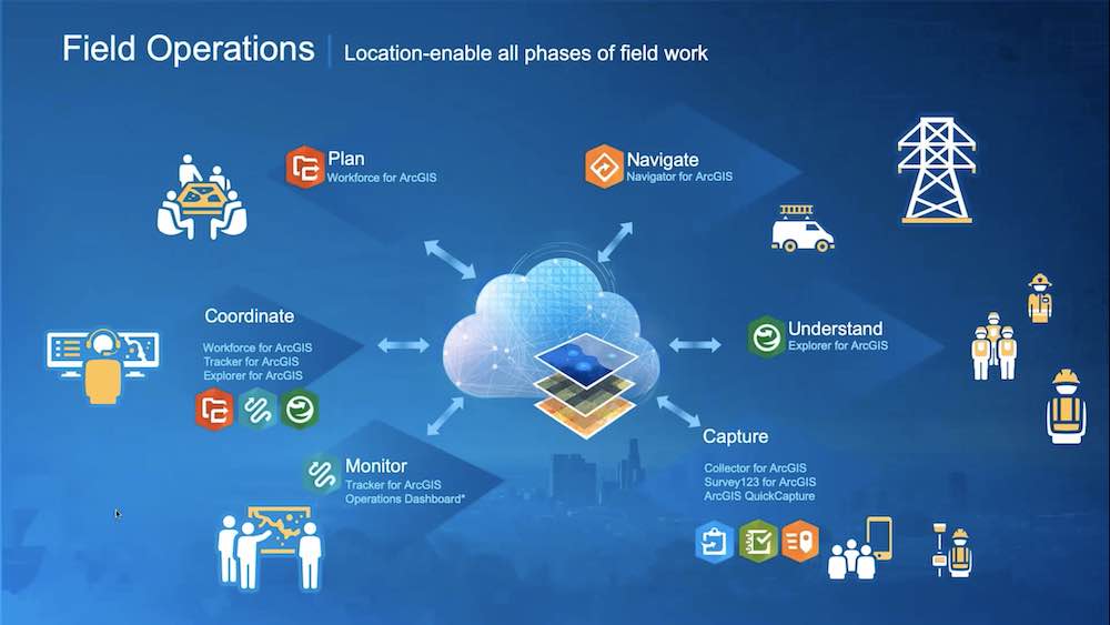
So this is just a slide outlining some of the other apps that you may use to complete those workflows. Each of these apps can be used independently but they can help or be used by one, or many together. That can improve the efficiency of your larger field data collection and/or acquisition processes, and improve the visibility of ongoing activities by monitoring that as it progresses. They also aid in sharing that information and delivering that to your project stakeholders or customers.
As Marc mentioned, there are a lot of environmental challenges to capturing data accurately in the field, so some of those examples may be areas where it’s hard to reach due to safety reasons, or your environment is challenging. Maybe you’re working under dense tree cover or you’re in a built environment where you’ve got lots of tall buildings that are interfering with the quality of the GPS signals that you’re getting. We partner with Eos and Laser Tech to support additional capabilities and workflows to ensure that you can collect highly accurate information quickly and safely in these types of difficult environments.
At this point, I’d like to turn it over to Sarah to talk about Eos Positioning Systems and the laser offset capabilities.”
About Eos Positioning Systems and the Arrow Series®
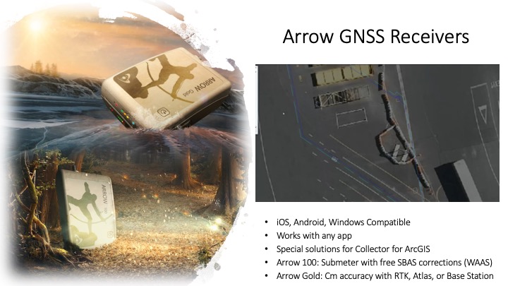

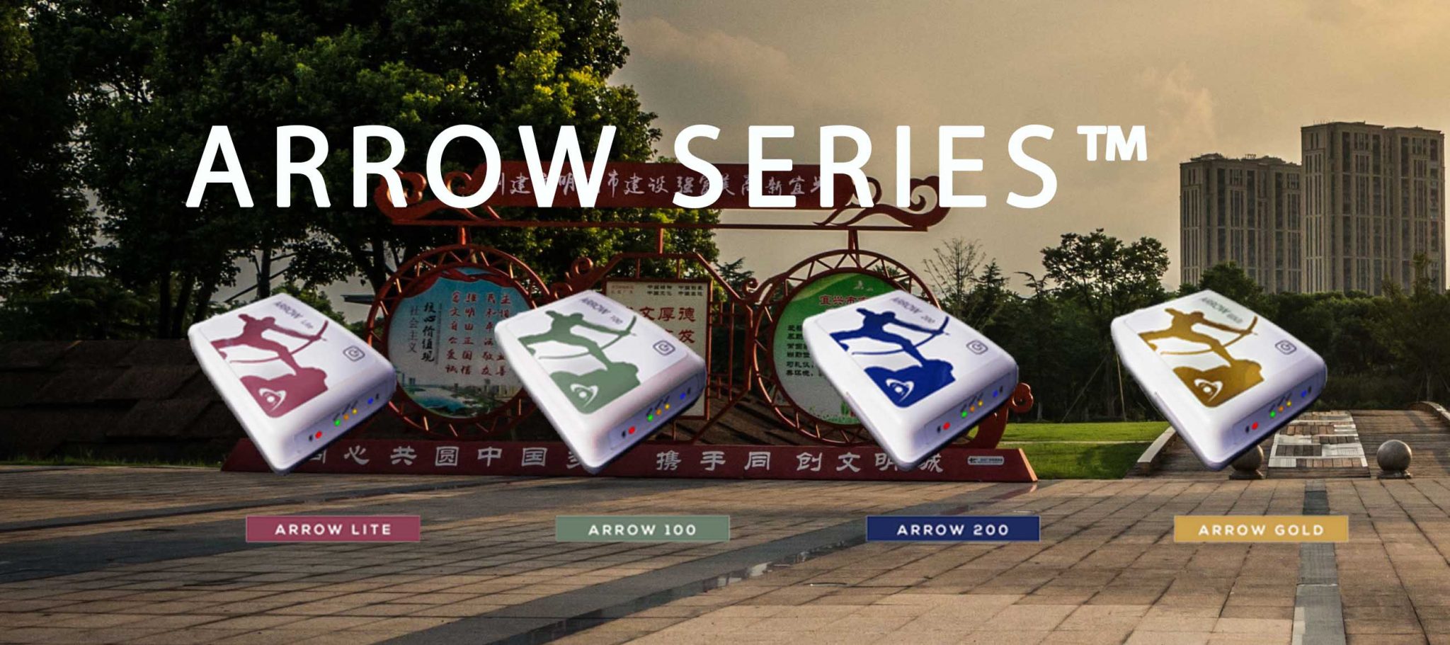
SARAH ALBAN: Thank you so much Doug. Eos Positioning Systems is an Esri Silver Partner, and our technical team was credited with creating the world’s first GPS receiver that is Bluetooth capable. It can work on any device and it achieves a centimeter accuracy.
What you see on the left is actually two of our most popular receivers; you’ve got the Arrow Gold, which is a centimeter unit, and the Arrow 100, which is our sub-meter unit. On the right, you see a video from one of our customers; this is made by a guy named Frederick at the Port of Auckland. I’ll go into a little bit of detail about what Frederick is showing us there.
A background on GNSS
Before I do that, I want to address that GPS and GNSS might both be used interchangeably in this webinar. But GPS could be considered like the U.S brand of GNSS — those are the positioning satellites that the U.S. government launched. You also have GNSS satellites from Europe with the Galileo satellites, you have the Russian satellites from GLONASS, and you have the BeiDou satellites from China. Most of today’s advanced receivers can access or lock on to satellites from all of those constellations.
So what you’re seeing in this video here, that blue dot actually represents the antenna that you see in the video portion and that antenna is receiving your GNSS satellite positioning from the GPS, the GLONASS, the BeiDou, and the Galileo satellites.
That initial position is being further corrected down to the centimeter level of accuracy through an RTK connection. And you might have caught a glimpse of the Eos Positioning Systems app, Eos Tools Pro, which is just a free app that’s allowed Frederick to connect to his local RTK network.
What he’s doing here is pretty cool. His position and the satellite signals are being captured by the antenna, or rather received, they’re been cabled into his Arrow Gold receiver on that range pole, and then that all of that location is being Bluetooth sent to his iPhone®, where it can be captured and used in Collector which is what you’re seeing on the screen.
So you can see where his dot is right on the corner of that yellow rectangle in the real world. It’s pretty cool because now he’s going to move it to the other corner of the rectangle, and that’s moving with high precision in his Collector. He can communicate directly with the engineers back in the office that the stuff happening in the field matches the designs that they have.
Laser mapping workflows
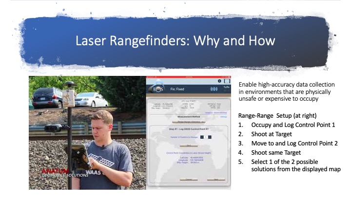
So what you’re seeing in this video is Tyler going through one of the workflows that Mike George, the next presenter, used in some of his use cases. He’s going through a workflow we call the Range-Range workflow. What it means is that he’s gonna stand on his initial control point, just take the location of where he’s standing, then he’s gonna shoot his asset. That asset might be a manhole. He’s gonna move to a second control point, and while he’s doing Eos Tools Pro, which is what you see on the right side of that screen with his iPad® that’s showing, is gonna walk him through those steps.
When he moves to his second control point, he’s gonna do the same thing, he’ll take the location, he’ll shoot the same exact target. So, in this case, we’re imagining it’s a manhole. And then Eos Tools Pro is going to provide him an option based on the control points he’s taken and the target that he shot. So, which of the two points represents the location he wants to log in to Collector. You can see it’s calculated two possible points where those intersections are; he’s gonna select the one that represents his target in the field, and then he’s gonna send it through to Collector by hitting the send button and it goes straight through Collector to ArcGIS Online.
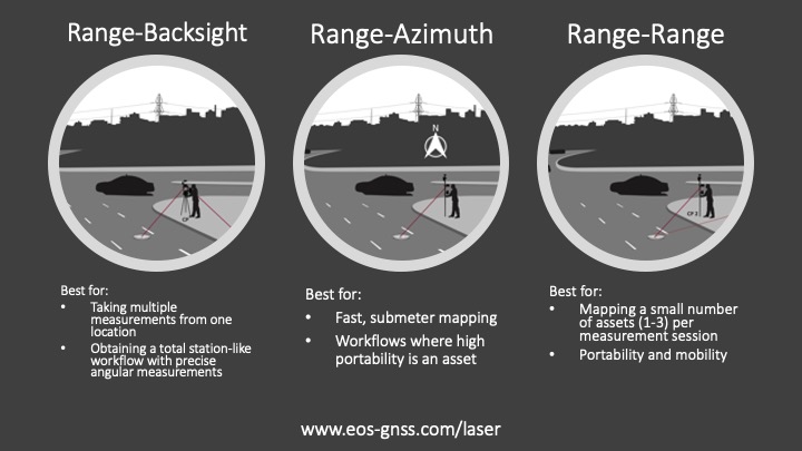
There are actually a couple of other workflows that people can choose from. There’s Range-Backsight; this is good if you want to stand in one spot, calibrate once and be able to shoot a lot of points. Range-Azimuth is good if your field crews have to be agile and speedy. All of them have slightly nuanced setups to how you would use them in the field.
On our website, you can find more how-to articles, how-to videos like the one you saw, and the specifications for the field gear. But now I’m gonna pass it over to Mike George.
Mike is a project manager with DDSI, and they do design, drafting and surveying. They were one of the earliest adopters of this laser mapping solution.
Eos Laser Mapping with ArcGIS Collector
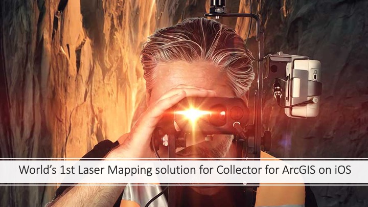
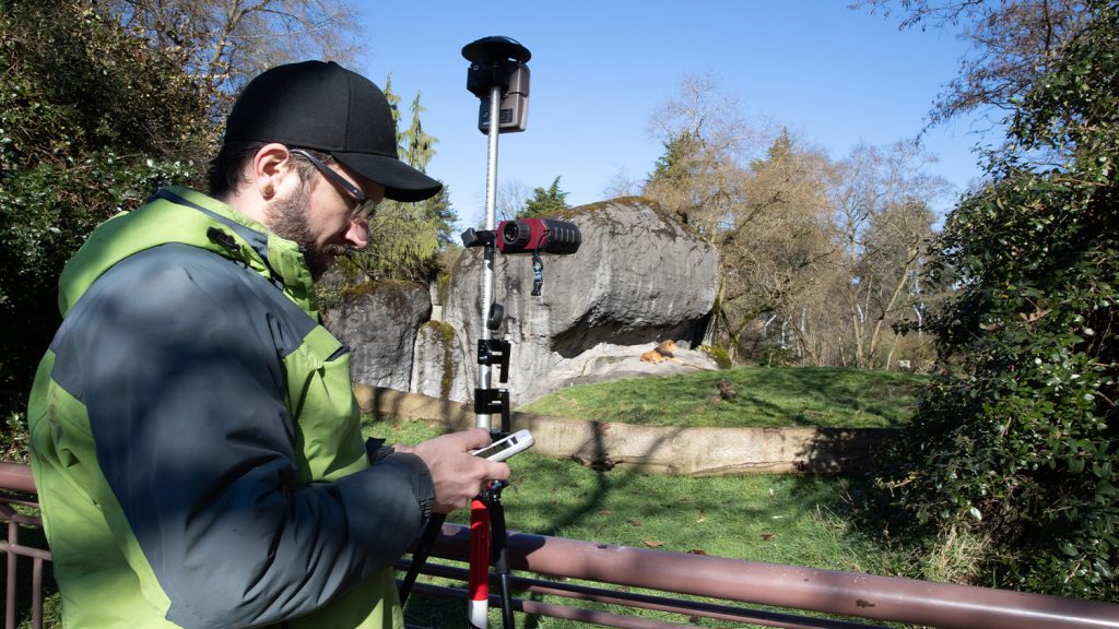
Because so many of our customers choose to use Collector and iOS® devices, we’ve released a lot of solutions to work with those technologies. Two years ago, we released the world’s first laser mapping solution for Collector on iOS. This was actually the result of a three-way partnership between Eos for the GNSS or GPS, with Laser Tech for the rangefinders, and with Doug’s Collector team at Esri. The solution allows you to capture an asset, whether it’s a utility locate or an irrigation valve, something that you don’t want to physically stand on top of in order to capture it, with high accuracy in real-time.
So some situations that Doug alluded to where you might want to do this. You can imagine if it’s an unsafe environment like you’ve got a manhole in the middle of a street and you don’t want to send a field crew person to stand on top of that, or you might just have an irrigation valve that’s underneath heavy foliage and you can’t lock onto satellites when you’re underneath it. You could also imagine this working in downtown Manhattan where you’ve got a lot of buildings, and you’d prefer to stand in an area where you have open skies and just shoot your asset from afar but retain that centimeter level of accuracy.
About DDSI Global


MIKE GEORGE: Perfect, thanks Sarah.
Well, first off, I just want to say thank you to Esri and Eos Positioning Systems for putting this all together today and a special thanks to all of you for attending our webinar. As Sarah mentioned, my name is Mike George. I’m one of the project managers here at DDSI and I’ve been in the geospatial business for almost 21 years now. I started off by mapping trails and Jeep roads here in Colorado for use in future forest service management plans, and I pretty much one way or another have been involved in the field data collection side of the industry for the majority of my career.
So here’s the agenda that we’re gonna be going over today. We’re gonna talk a little bit about the technology that was employed. I’ll highlight three case studies where we’ve recently implemented this new workflow, where we are applying all this new high accuracy technology, and then some examples of how we’re pulling it all together with GIS and CAD.
So just a quick summary of our company. As Sarah mentioned, we are a design, drafting and survey firm and we’re licensed in 12 states. We’re also proud to announce that DDSI is celebrating its 20-year anniversary this year. Our headquarters is in Tulsa, Oklahoma, then we also have field offices here in Denver, Colorado, Carlsbad, New Mexico and in Midland, Texas.
Our groups oversee anywhere between 20 to 30 field crews collecting accurate survey data pretty much on a daily basis. We primarily work in the oil and gas industry, where we provide survey services to all phases of construction to midstream operators. This includes preliminary routing, staking, landowner plats, plus as-built and after-built data capture.
In the wireless telecom space we partner with architecture and engineering companies responsible for installing new wireless infrastructure. We provide the exhibit and easement documentation to get the projects approved by the local municipalities, and some of these projects are the new site builds, rooftop surveys and easement designations. We also work with civil engineering firms for commercial and residential projects. These include Alta’s land survey plats and survey-grade data for remodels and new construction.
Technologies employed and how they were implemented
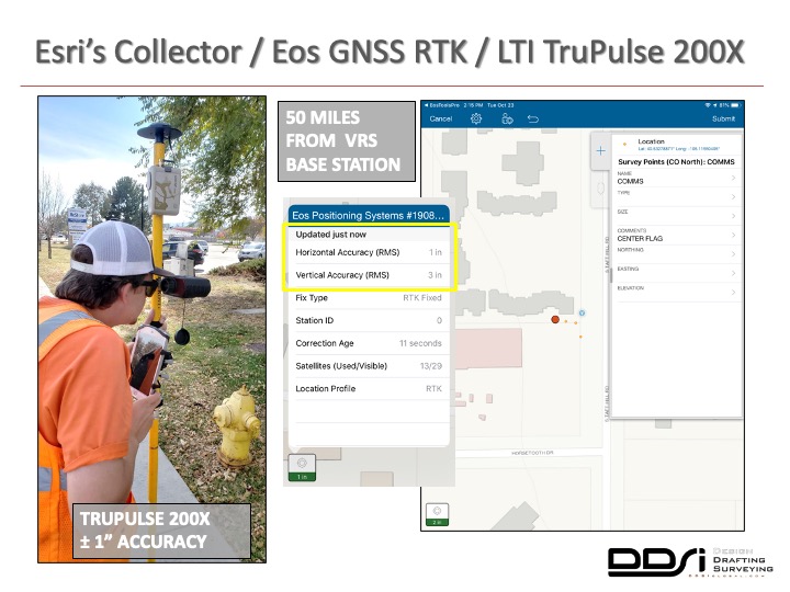
So, here’s a brief overview of some of the technology employed for this presentation. So, the software that we were using for these projects were ArcGIS Online, Esri’s ArcMap, ArcGIS Pro and AutoCAD Civil3D. The mobile apps were ArcGIS Collector and Eos Tools Pro. The RTK Global Navigation Satellite System (or the GNSS) was the Arrow Gold receiver by Eos, the laser rangefinder was the TruPulse 200X by Laser Technologies, and the real-time correction we were using was a virtual reference station set up. The data collectors with the iPad Mini® 4 Pro, Samsung S9 and Toughpad running Windows 10.
Technologies employed and how they were implemented
So, here’s a brief overview of some of the technology employed for this presentation. So, the software that we were using for these projects were ArcGIS Online, Esri’s ArcMap, ArcGIS Pro and AutoCAD Civil3D. The mobile apps were ArcGIS Collector and Eos Tools Pro. The RTK Global Navigation Satellite System (or the GNSS) was the Arrow Gold receiver by Eos, the laser rangefinder was the TruPulse 200X by Laser Technologies, and the real-time correction we were using was a virtual reference station set up. The data collectors with the iPad Mini 4 Pro, Samsung S9 and Toughpad running Windows 10.
New Eos laser offset workflow
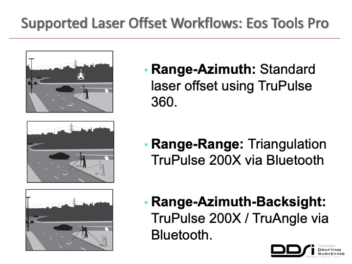
So as Sarah touched on earlier, there are three supportive workflows within Collector and the Eos tools Pro using LTI as laser rangefinders. The first is the Range-Azimuth – this uses the standard laser offset using the TruPulse 360. Since the TruPulse 360 already has an azimuth or compass built into it, you’re able to take multiple points without having to occupy two control points.
The Range-Range solution, which is what we’re going to be talking about today, is the triangulation solution that uses the TruPulse 200X via Bluetooth. The Range-Azimuth backsight also uses the same 200X rangefinder, but also pairs up with LTI’s true angle mounting system. This allows the system to acquire the necessary angle calculations without having to occupy multiple points. So, essentially you can set up in one location without having to do the triangulation and collect many points from the same spot.
So this is where the Collector, Eos and LTI laser offset routine has been a huge time saver for us. When we utilize the Range-Range offset routine, one field crew member can now capture our visibly obstructed assets very quickly and accurately without having to stop what they were doing and switch gears to a different piece of equipment.
Range-Range intersect workflow: step by step
We can go ahead and move to where we have a clear view of the sky, obtain two accurate control points, and produce the required laser offset. So here it’s still the same flags that we can see over here. Here are the pedestals that were obstructed by that same tree. Here, you can see easy it is to start the laser offset routine from inside ArcGIS Collector. The first step of the routine is now included out of the box within Collector, allowing us to quickly acquire the required control points and then accurately capture the offset of the asset. Notice the location of the control points safely occupied outside the dense vegetation cover and the approximate location of that same point.
From there, the workflow moves over to the Eos Tools Pro app, where once both the control points and the laser offset shots have been captured, the intuitive Range-Range intersection selection screen allows immediate feedback for which offset point is correct, and then be able to be submitted and saved to ArcGIS Online.
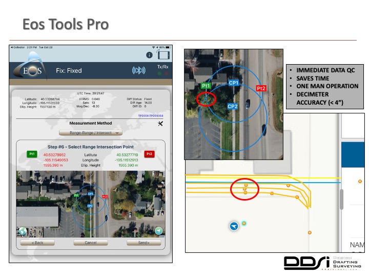
This once again saves us time and allows for quick quality control in the field. This will be able to be performed by a single crew member. This also provides the decimeter accuracy, which is essentially less than four inches, than we need to create our final deliverable. You can see the three points which were highlighted in that previous slide right here, pretty much showing up exactly in their same location where they were posted. We then create the correct utility pipeline features from those offsets in the field, whether it’s a fiber-optic cable, a water, a gas line, etc. and store those in our hosted ArcGIS Online account. This eliminates the guesswork back in the office from only a multitude of points being turned over to our drafting department, sometimes in one of our other offices, which was our workflow before implementing this new offset data capture process.
This is where we’ve got the triangulation; these are the screenshots we took in the field so it showed up exactly where we were looking for it. It gave us immediate feedback from the field, allowing us to know right away, which was the correct point to use and we knew that it was the right location.
Managing data in ArcGIS Online
So, as most of us are aware, Esri provides multiple ways for users to manage their data. We choose to host ours, our ArcGIS Collector projects, in our ArcGIS Online account. That’s allowing our other office staff to be able to view and retrieve the data in just about whatever format they need. ArcGIS Online allows for the multiple ETL formats to extract, transform, or load options without having to use another third-party software. Since most of our final deliverables are drafted in AutoCAD Civil3D, being able to directly download a shapefile or even in a CSV for example, without having separate staff members process the data, this saves us even more time.
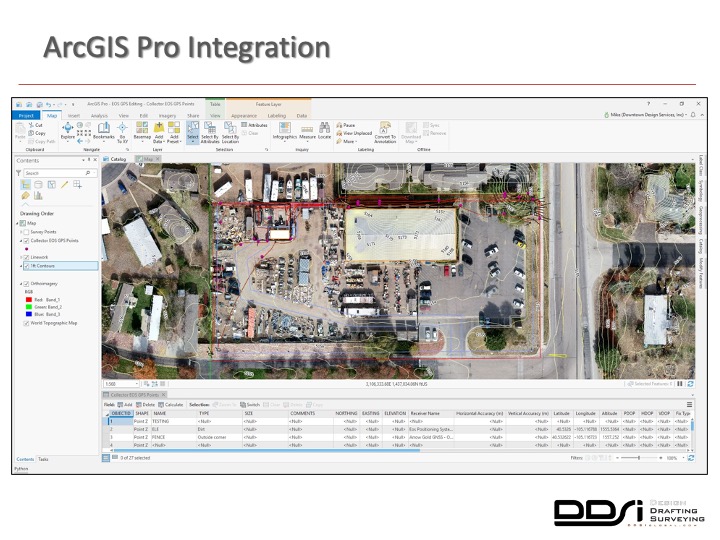
So here, we’re looking at a mesh of all the data captured from this project digitized and processed. The survey accurate parcel boundary is tied down, utilities located here by the Eos, Collector, and LTI offset solution, easements drafted from the client provided title commitment, one-foot contours extracted from our post-processed drone data, all laid on top of our high-resolution imagery also collected by a drone and viewed in ArcGIS Pro.
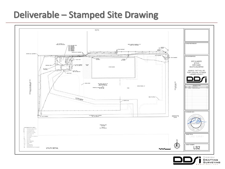
You guys kind of see a little bit extra how this all came together. From there, we add any additional axis and utilities missed requested by the client to further build out the lease area. They can then turn over this final deliverable to the local municipality with our stamp and signature from one of our licensed surveyors for review and approval of the project.
Case study: city parks survey
So, this next project I want to quickly talk about is a recent survey we completed at a local city park. The scope of work included capturing all existing features and spot elevations in a 25-foot grid and in each sidewalk entrance. We were also required to collect the privately located utilities, irrigation sprinkler heads, and valve control boxes for approximately a five-acre location. The purpose for us was to be able to turn over the deliverable and data to an architecture firm for them to design new ADA compliant ramps and overall park improvements.
As we talked about before, we’re never quite sure what we’re gonna find until we get there and this turned out to be another situation where the Collector, Eos, and LTI laser offset solution became a perfect tool for the job.
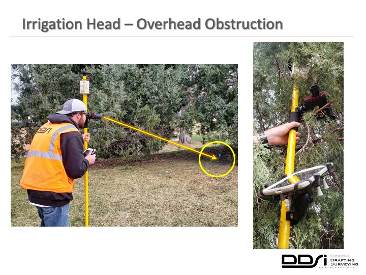
Once again, we’ve got some dense vegetation locations in the park. Once we got on site, there were quite a few irrigation valves and sprinkler heads that were within the obstructed areas. In this specific scenario, you can see the irrigation that was heavily obstructed for us to be able to physically occupy the point. But just 10 yards away with a clear view of the sky, we’re able to perform the offset routine without having to stop or switch gears and potentially use our total station to acquire the single point feature. From the picture on the right, you can easily tell how obstructed the receiver was to the clear view of the sky, allowing us to capture the point and stay within the client’s required accuracy threshold.
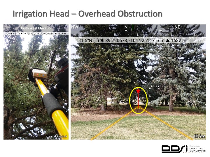
The second example is from the northeast corner of the park and you can see about the same dense canopy obscuring the Clear View by these pine trees. We could have tried to stay in the same location, potentially trying to average 30 to 40 points and hope for the best, but why chance it? Once again, we can step out in the clearing, allowing us to gain a fixed VRS position with sub-inch control accuracy, then perform the laser offset routine. A single crew member was able to solve the problem without having to stop, reassess, and potentially ask for help to acquire a single point feature.
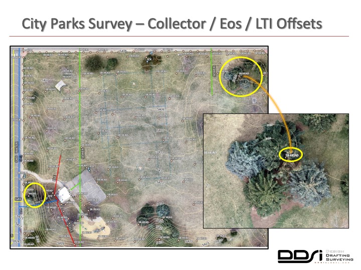
Once again, here’s all the point features and underground utilities we collected with our Collector, Eos, and LTI offset solution overlaid on ArcGIS Pro. Within our highlighted area, you can see how far back that irrigation head really was; it looked deceiving from the previous photo that looked much closer to the southern edge of that location. By being able to collect the located utilities and irrigation features, then post it to ArcGIS Online, then send it directly into AutoCAD Civil3D by a simple shapefile download. It was a huge time saving for us. The less hand-holding our project managers and field crews have to do with our drafters and produce our deliverables, the more profitable the project will be.
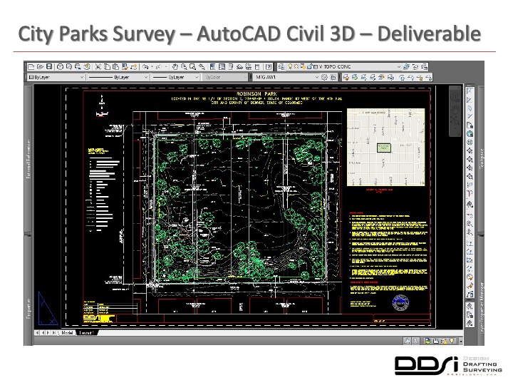
Here’s a screenshot of the final deliverable required by our client with a stamp of signature, and you can see here where the level of detail was necessary.
By using the Collector, Eos, and LTI offset routine, we were able to deliver this project on time and under budget.
Case study: engineering site survey
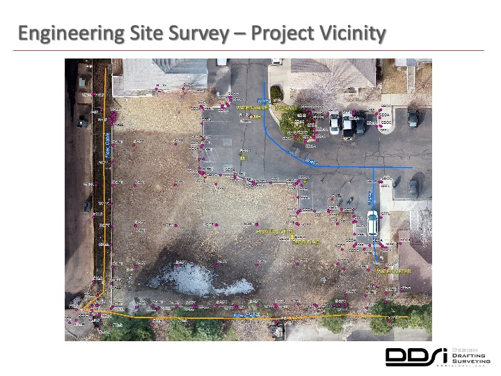
Very quickly, this is the last project I want to talk to you guys about. This was recently completed a couple of weeks ago for one of our engineering clients. All the points you see here in magenta were captured using our total station and be able to post-process and deliver engineering quality data for their design purposes. The utility locates once again captured by our Collector, Eos, and LTI laser offset routine, putting an entire set of offsets to create the common fiber polyline here the southern end where it was obstructed by thick rows of trees and bushes.
So to make the quick data comparison, I captured two points – one physically occupied and then the other as a laser offset to Q.C. the data back and the offset to kind of do my own Pepsi challenge.
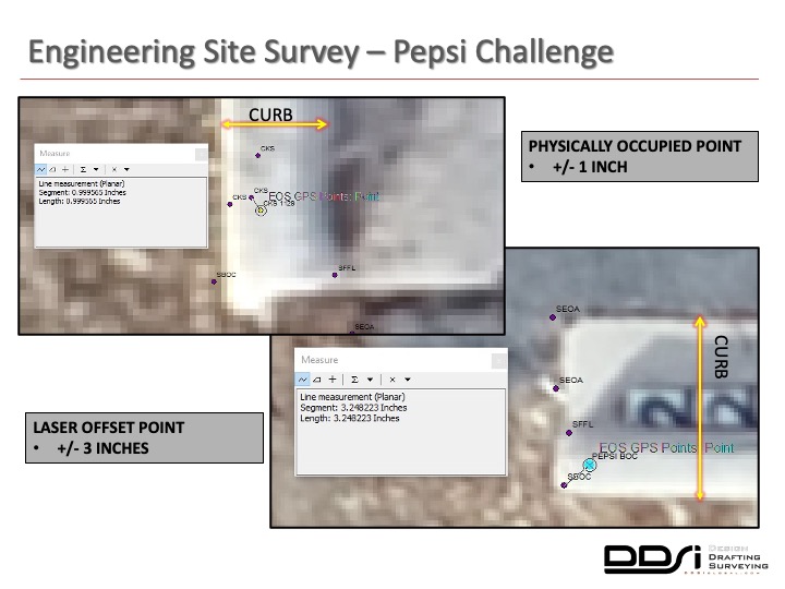
As you can see from the physically occupied point, we got less than an inch of error from the same point collected from our total station; it’s well within the range of GPS error, GNSS error, and the possibility of the survey. Survey rod was not held perfectly plumb, and then the laser offset where we shot the same back curb location was sub-decimeter accuracy and for the offset, so less than four inches.
So I know this is not truly a scientific test and I’m sure I could have gotten even more active results by doing additional testing, but to be completely honest, we ran out of time. The point is if you’re looking to collect your own assets, aren’t able to tie into a base station or virtual reference station, getting sub-inch real-time, no post-processing accuracy has now become a reality for everyone.
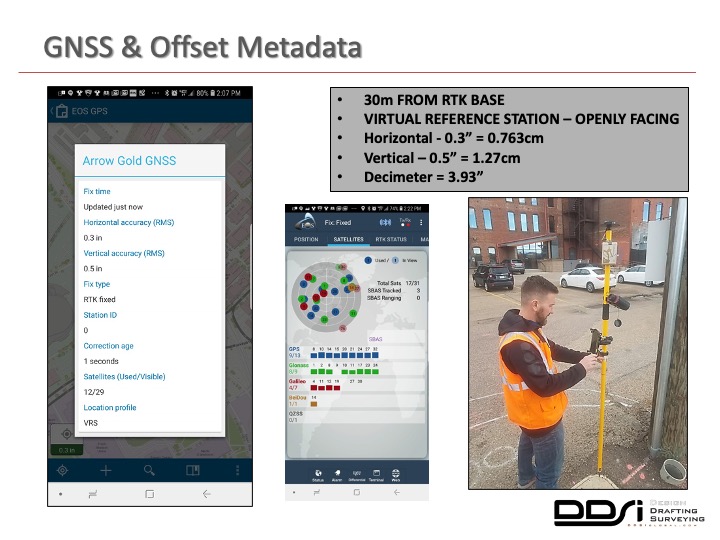
Here’s this quick screenshot of the accuracies that we were getting when we are tied into our virtual reference station. Note the horizontal, vertical, being put out by ArcGIS Collector and then inside of Eos Tools Pro and as the technology of GNSS satellites continues to evolve, this is only going to get better.
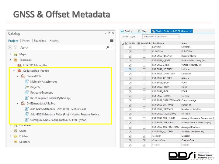
I quickly want to note that a host of GNSS and laser offset fields are now available out of the box on ArcGIS Pro. You can add this toolbox to catalog in ArcGIS Pro, run the scripts to your desired feature class within your geodatabase, and you’ll see these automatically populated when data is captured in the field.
DDSI Global: quick recap
Tight budgets for us require a little room for error. Every project site is unique, requiring different tools. There are continual field challenges that we don’t know until we get on-site, whether it’s urban corridors or dense vegetation. Collecting accurate data with only one crew member is a huge key for us. Being able to bring your own device and to tie in Esri’s apps to solve problems on the fly has also been a huge time-saver. The RTK laser mapping acquires the high accuracy points that we’re looking for, allowing us to get the final deliverable on time and under budget.
Once again, I would just like to thank everyone at Esri and Eos positioning for inviting me to participate in this webinar today. Hopefully, this has peaked a few ideas on how you can implement this type of field collection workflow to ideally quickly solve some data capture problems, of course, save some time and money within your organization. With that, I’d like to pass back on to Marc and begin the question and answer portion. Thanks everyone.
Q&A
MARC GOLDMAN:
So Mike. In that project, I love the outside warehouse portion. I half-expected a junkyard dog to be chasing you guys around.
MIKE GEORGE:
It was that, yes.
MARC GOLDMAN:
You know on that project in particular, what the greatest value from that setup? You did a lot of work in that little space there.
MIKE GEORGE:
For sure. So as I kind of touched on, it really comes down to time saved on both ends, both in the field and in the office. The other key is the ease of use and the ability for me to get even our most junior field crew operators up to speed quickly. This whole workflow takes very little training and very little time to get set up and it could be essentially passed on to anybody and anyone in the organization and it’s all contained within the same setup so once you get it essentially configured attached to your pole and you can head out up and running in no time.
MARC GOLDMAN:
So what are the parts and pieces? Could we go over them?
MIKE GEORGE:
Well, you have the receiver set up, and then you need to attach and calibrate your TruPulse 200x offset for your rangefinder. And then tie that all together with your data collector. For our case, we use the iPad; it’s just the most functional usage for all the software that ties into it. Once you get all those set up with your survey pole, you can begin your project in essentially little time.
MARC GOLDMAN:
You know I’m familiar with total stations and other expensive technologies, but you know, this seems so much more agile.
MIKE GEORGE:
It is for sure. It’s way more agile. What I like best about it is that even as you’re physically occupying the points that are in clear view, you get to that situation where you’re under a canopy or it’s under a building, you run the offset and collect the two points from the outside and it shows up right up against the building in the base maps, save it, and move on to the next point
MARC GOLDMAN:
Doug, you mentioned something. I think all of you touched on different levels of accuracy from one centimeter to about 10 centimeters, and it’s not clear to me. What is the difference in the set up to get better accuracy or is that the method in which you shoot your points with multiple control points or such. What’s causing that variability?
DOUG MORGENTHALER:
Mark, it’s a great question. So a lot of that boils down to the setup Sarah outlined. There were three different methods, some of those do have more accurate calibrations with an angle encoder. So you can get a very precise angle for that offset. And, obviously, also the distance in which you are shooting, although for most cases the laser rangefinders that Laser Tech provides are quite accurate. So those are just a couple of factors that can influence the level of accuracy of a position you would capture with this solution.
MARC GOLDMAN:
Okay, it makes a lot of sense. Let’s see, one question. This might also be for you, Sarah. I want you to talk a little bit about the virtual base station.
SARAH ALBAN:
Yeah, it actually passes on to Mike because he has a lot of field experience in using it.
MIKE GEORGE:
In the front range of Denver, we were essentially blessed by having an openly facing ,unicipality provided virtual reference stations. These are not publicly available everywhere, so you’d have to check where you’re located and see if that’s a possibility.
But here we have two gracious local governments that openly face a virtual reference station that you can then tie in through the setup routine in Eos Tools Pro and ArcGIS Collector. Essentially you put an I.P. address and the port, and once you have that set up and you tie into it with a data connection, so whether that be a tie-in from your data collector that has its own wireless connection, or you connect to your Wi-Fi hotspot, once you have that set up then you receive those offsets and that gives you that centimeter accuracy on the fly.
So you’d have to check in your local area if that’s available. If not, there are some paid services out there that you can look at, but I wouldn’t be able to speak on which ones are available in each area. In Denver, we have those that are openly facing.
SARAH ALBAN:
Yeah, Denver is very well-equipped. It’s a good place to be if you want to do this kind of work. If you’re curious about what’s available in your area, fill out the Eos contact page on our website, and we’ll give you feedback. If you’re specifically curious about things like – Is there an RTK Network? Is there a VRS? Is there something in your area. Just ask us, and we can probably find somebody in that area that can assist you.
MARC GOLDMAN:
You know, you almost glossed over what sounded like a crazy level of productivity increase here. Where two people would have to go out with rather expensive hardware, the crew of two is now going out and doing two projects. A 100% improvement in productivity, I mean, is that really what you’re seeing?
MIKE GEORGE:
For us, the ultimate goal is to complete two sites per day for our 20% return on investment. At minimum, it’s saving us at least two hours in the field per project, and then it can take us anywhere between two to ten hours for each one of our project sites to draft back in the office. So we’re saving another two hours on the office for the drafters by the elimination of the hand-holding with the questions. This is because we’ve got the high-resolution imagery in the background. So instead of just turning over a bunch of points on a blank screen and then asking our drafters to figure that out and create those deliverables that I was highlighting, we use the workflow. This whole workflow has essentially saved us that 20%.
MARC GOLDMAN:
Yeah that’s probably being conservative.
MIKE GEORGE:
Yeah, pretty much.
MARC GOLDMAN:
You know we’re going to close this off. Thank you for the fantastic presentations, Mike, Doug and Sarah. And thanks for those who joined us tody, thanks for participation. This concludes the program.

