
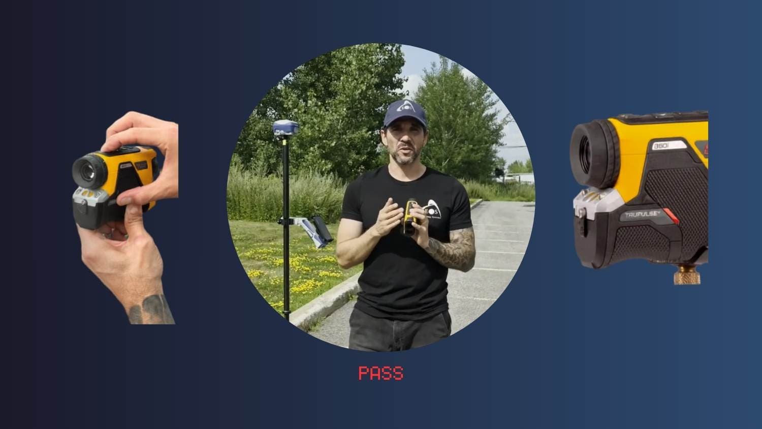
Before using Eos Laser Mapping for ArcGIS® with TP 360i (TruPulse® 360i) from Laser Tech (LTI), you’ll need to calibrate the TP 360i compass. In this video, Eos Positioning Systems Technical Support Manager Alvaro Paez performs the TP 360i calibration so you may see what the process entails. Play the video and follow along with the transcript below when performing your own calibration.
Important: This video is not intended as a replacement for reading the Laser Tech TruPulse® 360i Compass User Calibration Procedure. We strongly recommend you use this video only to supplement LTI’s official documentation.
Note that the TP 360i should be re-calibrated at each new job site, after replacing the batteries, and any time the checkmark starts blinking (more on that below).
Video Transcript: “Calibrating the TP 360i Compass for Use with Eos Laser Mapping™”
ALVARO PAEZ: Hey everybody, today we’re going do the compass calibration for the TP 360i (TruPulse® 360i) from Laser Tech, Inc.
Before beginning any laser [mapping] workflow with the TP 360i [and any Eos GNSS receiver], we need to make sure that the compass calibration is done correctly.
Before Beginning: Remove Any Items that Could Cause Magnetic Interference
So, to do that properly, just [first] step away from any magnetic interference. For example, your GPS receiver, your phone, your car keys —we’re going put these aside. Your watch is also important to remove, so we’re going to remove ours just for the sake of [being cautious].
When you receive the TP 360i, you need to do the compass calibration. [Until you do this,] you’re going to see — when you take a shot by clicking the “FIRE” button — that there’s a calibration that is pending. [If] there is a red check mark blinking on the top right of your screen, that’s going to tell you that your calibration needs to be done.
First: Find True North
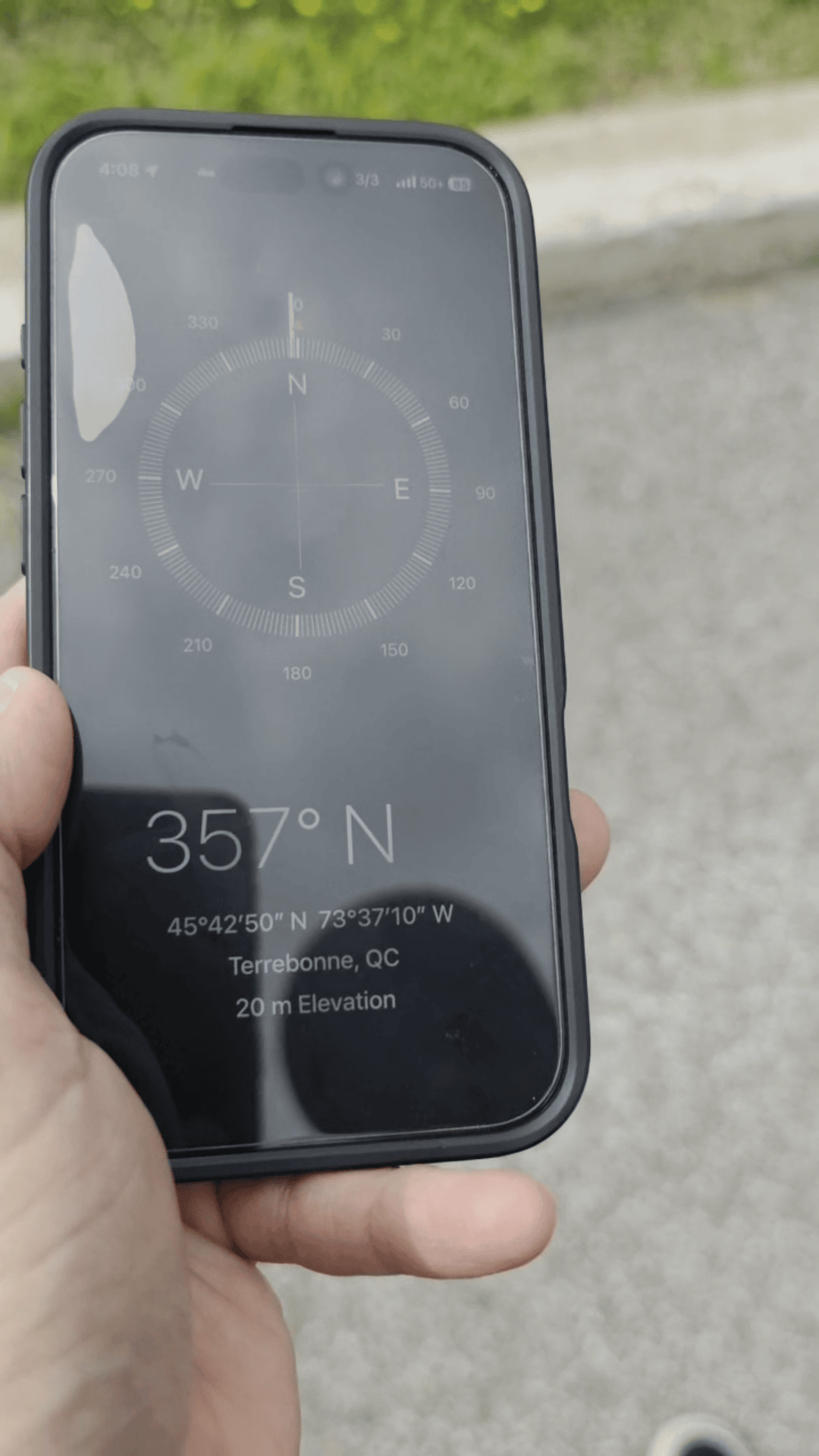
So, the first step to start the calibration [is that] you need to find the true north. [To do this], you can use the compass on your phone, like an iPhone®, or [by using a] real compass. So, I’ll show you right now.
So, if we found the true north, it’s more to the right side that way. Note: There’s a tolerance of about 10° degrees.
Second: Start the Calibration
Okay [recall that] we removed any metal or other objects that could create a magnetic interference. So right now, we’re going to start the calibration.
What we’re going to do first is hit the “FIRE” button to turn on the TP 360i. So, we’re going to hit the “FIRE” button. You should see some information when look [through] the lens.
Procedure from LTI (download as a PDF from the LTI website):
- Short Press Menu button to enter Settings menu.
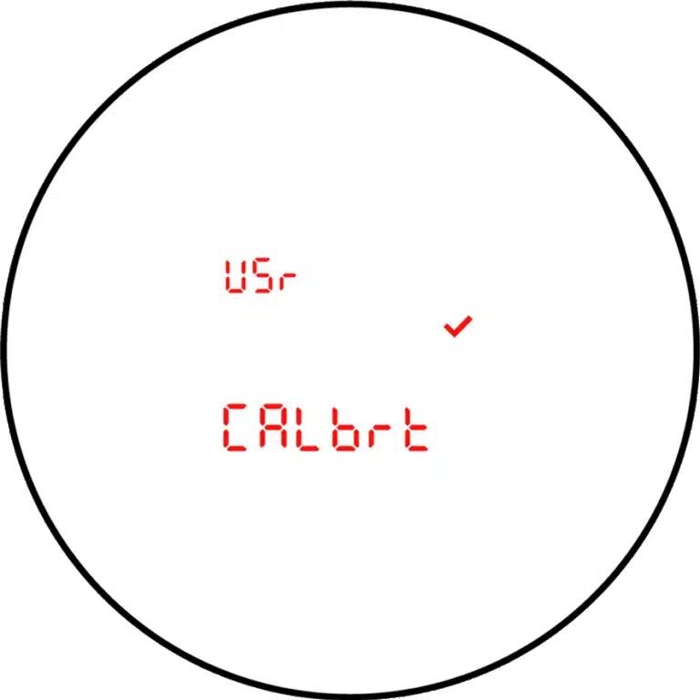
- Press Menu button to scroll to the User Calibration option.
- Press the Select button to enter the User Calibration options.
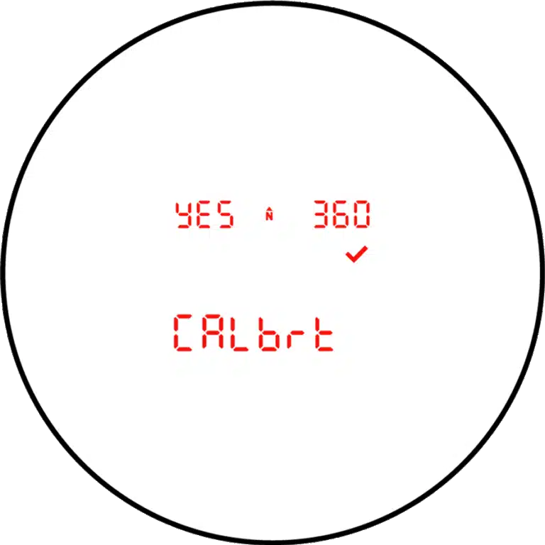
- Press Navigation buttons (arrows) to “Yes 360i Calbrt” display. Press the Select button.
- At each step, wait approximately 1 second before pressing the FIRE button. Then wait another second before moving to the next position. It is important that the unit is held steady when the button is pressed.
We have entered the calibration of the compass.
Next: Perform the 12 Calibration Motions
Now, you’re going to see at the bottom. it will be shown as “C1_Fd,” so we’re going to start the process one by one [of a series of calibration motions that calibrate various control points]. There are going to be 12 motions:
Notes:
- We’re always using the “FIRE” button.
- The “OCULAR LENS” refers to the rear glass piece where you put your eye.
- The “OBJECTIVE LENS” refers to the front glass piece you point at your target.
- Do not perform these steps without first consulting the Laser Tech TruPulse® 360i Compass User Calibration Procedure.
The 12 Motions Are as Follows:
Control #1: C1_Fd (Front)
The OBJECTIVE LENS points front to true north. Press the “FIRE” button.
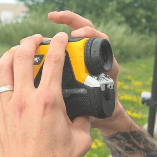
Control #2: C2_dn (Down)
Rotate the laser rangefinder lens 90° away from you so the OBJECTIVE LENS points to the bottom/ground. Buttons face true north. Press the “FIRE” button.
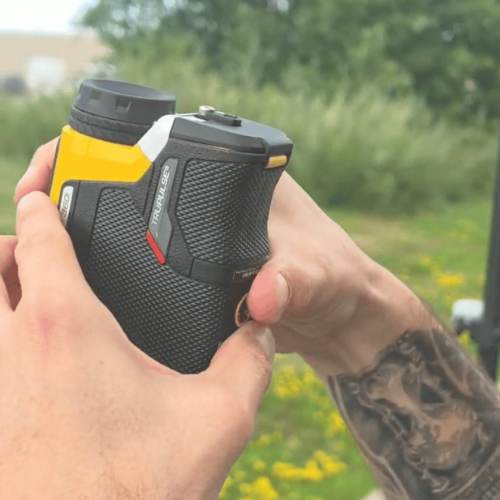
Control #3: C3_bc (Backward)
Rotate the laser rangefinder lens 90° away from you again. The OBJECTIVE LENS points backward at you, and buttons face the ground. Press the “FIRE” button.
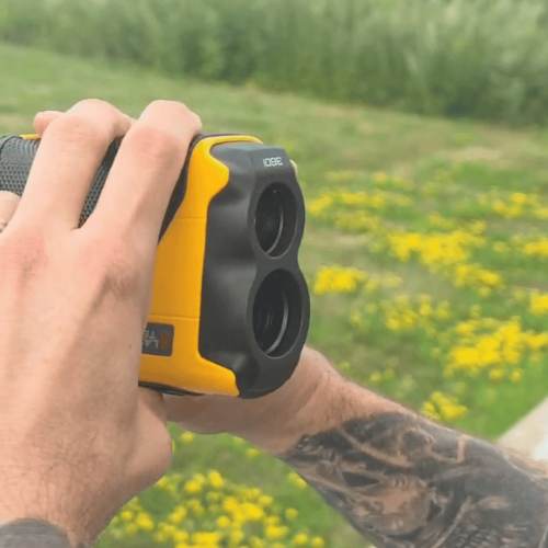
Control #4: C4_UP (Up)
Rotate the laser rangefinder 90° away from you a fourth time. The OBJECTIVE LENS points up toward the sky. Buttons face you. Press the “FIRE” button.
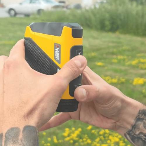
Control #5: C5_rF (Rear Front)
Imagine a vertical axis running from the OCULAR LENS through the OBJECTIVE LENS. Rotate the rangefinder 90° counterclockwise along this axis. Now lie the laser rangefinder flat, so that the OBJECTIVE LENS points true north, the OCULAR LENS faces you, and buttons face east (your right). Press the “FIRE” button.
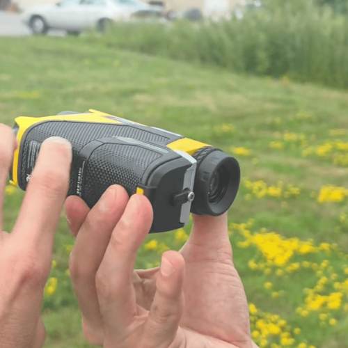
Control #6: C6_rd (Rear Down)
Rotate the OCULAR LENS 90° up and away from you so that the OBJECTIVE LENS points down toward the ground. The buttons continue facing east (your right). Press the “FIRE” button.
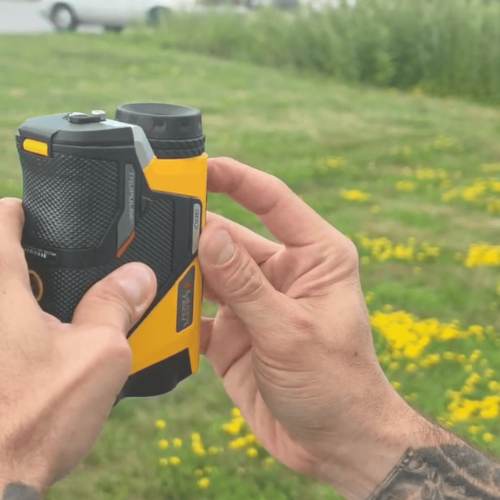
Control #7: C7_rb (Rear Back)
Rotate the OCULAR LENS 90° up and away from you again. The OBJECTIVE LENS points toward you. The OCULAR LENS faces true north. Buttons continue facing east (your right). Press the “FIRE” button.
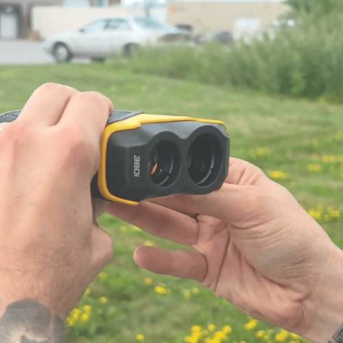
Control #8: C8_rU (Rear Up)
Rotate the laser rangefinder 90° away from you again, so the OBJECTIVE LENS points toward the sky. The OCULAR LENS faces the ground. Buttons face east (your right). Press the “FIRE” button.
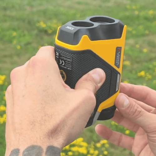
Control #9: C9_UF (Up Front)
Rotate the laser rangefinder to its original position, Control #1. The OBJECTIVE LENS points true north, the OCULAR LENS faces you, and buttons face the sky. Press the “FIRE” button.
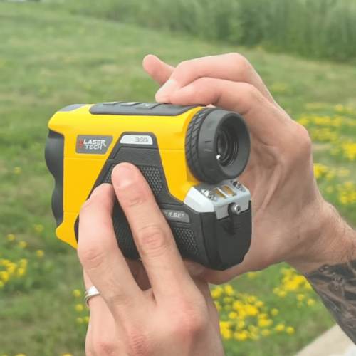
Control #10: C10_Ur (Up Right)
Imagine a vertical axis cuts the rangefinder in half from the sky to ground. Rotate the laser rangefinder 90° clockwise along this vertical axis so that the OBJECTIVE LENS points east (to your right), the OCULAR LENS faces west (your left), and buttons still face the sky. Press the “FIRE” button.
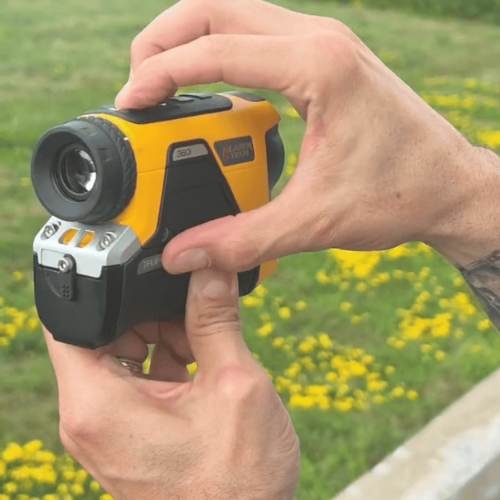
Control #11: C11_Ub (Up Back)
Rotate the laser rangefinder 90° clockwise again along this vertical axis. The OBJECTIVE LENS points toward you, the OCULAR LENS faces true north, and buttons still face the sky. Press the “FIRE” button.
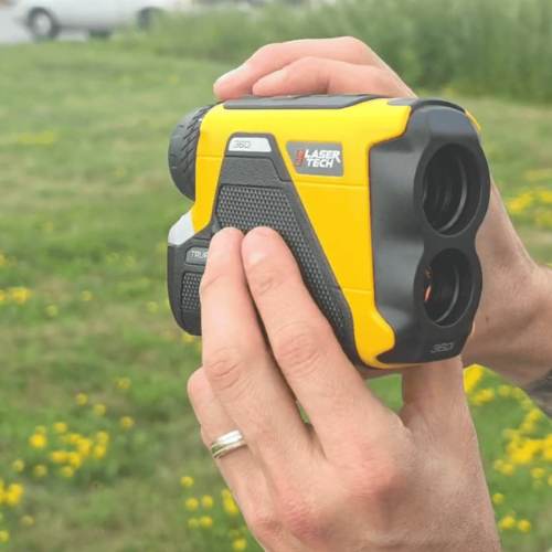
Control #12: C12_UL (Up Left)
One last time, rotate the laser rangefinder 90° clockwise along this vertical axis. The OBJECTIVE LENS points west (your left), the OCULAR LENS faces east (your right), and buttons face the sky. Press the “FIRE” button.
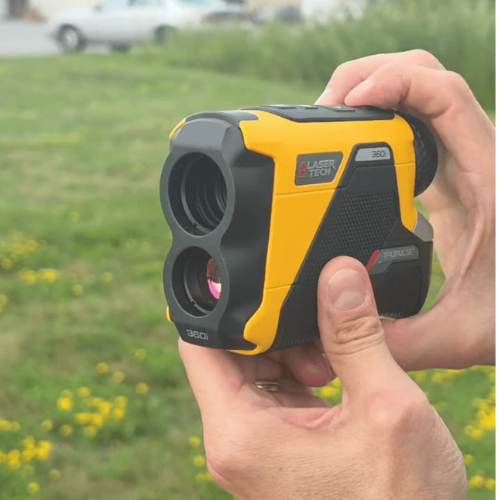
Finally: Confirm You See “PASS”
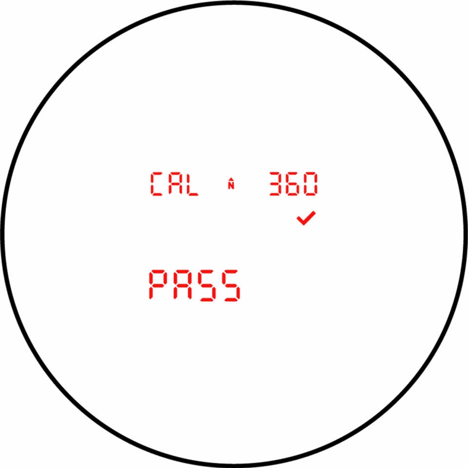
Once that is completed, you should see “PASS” on the screen of your TP 360i. That confirms the calibration is complete.
Explore Related Items
Field Demonstration: 3 Eos Laser Mapping Methods
In these videos, we demonstrate data capture using 3 Eos Laser Mapping methods: Range-Azimuth, Range-Backsight, and Range-Range.

Skadi Tilt Compensation™: User Manual
This manual guides you through the steps to enable, initialize, and begin using Skadi Tilt Compensation™. Requires a Skadi Tilt Compensation activation.