Have you ever wished you could stay in one spot and map all your assets? Imagine standing on a sidewalk with clear line-of-sight to an open sky and mapping a row of tightly packed gas meters on the side of an alley building, with centimeter-level accuracy.
The Range-Backsight method from the Eos Laser Mapping™ solution is the ideal setup for achieving this.
Terms of the Trade
What are we talking about when we say “Range-Backsight”? There are three terms you may want to know.

1. Occupied Point
An occupied point is the physical location over which your laser mapping solution is set. This is an important position, because it is only by knowing your current position that the Eos Laser Mapping™ solution will be able to deduce your offset positions of far-away assets. It is a good idea to select your occupied point in a spot that is both safe and has a clear line-of-sight to the sky and as many assets as possible.
2. Azimuth
An azimuth represents the angle to a line of sight, such as from your occupied point to the asset you are shooting. The azimuth measurement will be used to help calculate the coordinates of the far-away assets you are shooting. The azimuth is calculated during the calibration of your LTI TruAngle Angle Encoder (described below).
3. Backsight
In surveying, a backsight establishes the north reference or zero (0°) angle of an instrument on an occupation point. A backsight is a known reference or control point and is often the first point taken by an optical instrument in a survey. In the Eos Laser Mapping™ solution, it is a fixed point of reference that is used to calibrate the angle encoder to give true north azimuth measurements.
What are the Benefits of Range-Backsight Laser Mapping Method?
The Range-Backsight laser mapping method is the most efficient and most accurate of the three laser mapping methods. It is also ideal for when you intend to capture a large number of shots from a single location—with extreme accuracy. Once calibrated, you can capture any assets that are within range of the TruPulse.
The Eos Laser Mapping™ Range-Backsight method is similar to the measuring techniques and principles used with traditional optical measuring instruments, like a total-station for example. From an instrument/hardware standpoint a total station consists of the following:
- An electronic theodolite, which measures horizontal and vertical angles (azimuth and inclination, respectively)
- An electronic distance meter (EDM), which measures distance to the target asset
Similarly, the Eos Laser Mapping™ solution performs a total station-like workflow through the integration of the following instruments:
- The TruPulse® laser rangefinder, which measures the distance and vertical angle (inclination) to the target asset
- The LTI MapStar® TruAngle® angle encoder, which measures and calculates the horizontal angle (azimuth) when the laser is on focused on the target asset
New points (target assets) are calculated by measuring the angles and distances from the occupied point and doing some coordinate geometry to calculate the locations of the target assets. When required on larger project areas, this workflow can be used simply by establishing additional occupation points. This is beneficial, for example, for capturing assets along a corridor or right of way (ROW). The high-accuracy positioning of the Arrow GNSS receiver gives you an extremely versatile and accurate solution, and it is more lightweight and affordable than a traditional total station.
While the Range-Backsight laser-mapping method requires the most equipment of the three Eos Laser Mapping™ methods, it importantly provides an all-in-one package for extremely precise measurements that allow you to capture multiple assets from one location.
What Equipment is Required for Range-Backsight Laser Mapping?
There is a variety of hardware and software needed to perform laser mapping with the Range-Backsight method. Below is each required component and the basic function it contributes to the total solution:
- Eos Arrow Series® Receiver (any model) – Provides survey-grade GNSS location accuracy to the final captured points
- Eos Tools Pro (latest version) – Contains the brain of the solution and walks you through the field workflow; also manages your RTK or base station corrections for real-time survey-grade accuracy
- ArcGIS Field Maps (or ArcGIS Collector) (latest version) – Collects the data from the solution and stores this in an Esri ArcGIS web map
- LTI Laser Rangefinder Equipment:
- LTI TruPulse 200X Laser Rangefinder – Shoots the points and sends this information to Eos Tools Pro
- LTI Mapstar TruAngle Angle Encoder – Calculates the azimuth from the control point to the asset being collected, which is a required measurement to calculate the asset’s precise coordinates
- iOS® Device (iPad®, iPhone®) with version 11 or later – Runs the mobile apps and connects the hardware via Bluetooth®
- Android Mobile Device – As of March 29, 2022, this solution will also run on Android mobile devices
- Range Pole (with Bipod Legs) or Tripod – Either a range pole with a level bubble and bipod legs or a tripod. This will be where you mount all your hardware.
- LTI Arrow TruAngle Mounting Bracket – Mounts the TruAngle to your range pole
Once you own the required hardware and software, the solution itself incurs no extra fee or subscription. You can simply set up your equipment and begin to use this method.
Watch this video to learn how to mount the Range-Backsight hardware:
Configuring the Eos Laser Mapping™ Solution
After you have set up the hardware on the range pole (with bipod) you will need to do some basic configuration of the different the devices; the Arrow Gold® GNSS receiver, TruPulse 200X laser rangefinder, and the TruAngle angle encoder.
- Arrow GNSS Receiver & Eos Tools Pro: Turn on the Arrow and allow the receiver to acquire satellites. Now is also a good time to set a few parameters in Eos Tools Pro (e.g., RTK or NTRIP setup, status alarms, GEOID models, datums shifts).
- TruPulse 200X Settings: There are three settings that need to be made on the TruPulse laser rangefinder. First, use the “Mode”, “Arrow”, and “Fire” buttons to set up the Bluetooth® mode to “Encoder” (EnC) mode. Second, set the “Units” setting. This needs to be meters. Lastly, put the laser in either horizontal or slope distance mode.
- TruAngle Angle Encoder: Power on the TruAngle angle encoder. The display will show “ind” which is the Index menu. Rotate the TruAngle 360o until the numbers are flashing “0.00o”. Press the “On” button to store the calibration in the direction you want.
Calibrating the Equipment
With Range-Backsight you will need to take what is called a “backsight point” before you begin collecting data. This is a necessary step to calibrate the TruAngle angle encoder (which only counts precise degrees of rotation from 0 to 360 but has no reference to North) for a true azimuth reading.
Here is how to perform the calibration:
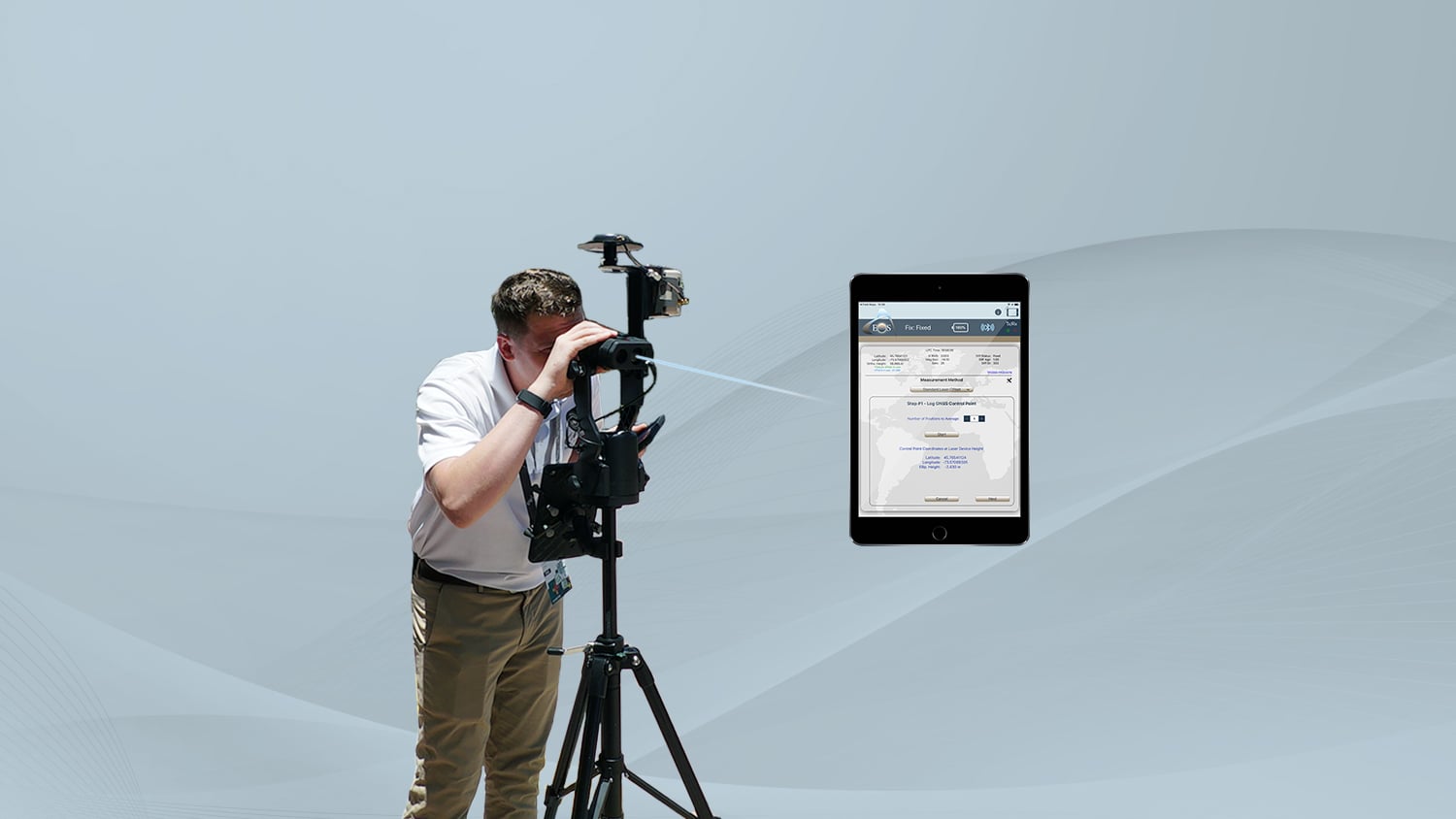
- Occupy (physically stand at) your Backsight Point. Log GNSS Point. You can choose any point as the backsight. But it helps to use spray paint, a cone, or even just a rock to mark the backsight you’ve chosen. Using Eos Tools Pro, store the backsight coordinates.
- Move to a Control Point. Log GNSS Point. We recommend moving at least 20 feet away from your backsight to a Control Point. You can pick any second point to serve as your Control Point. But it should be a spot from where you can see all of the assets that you would like to collect and at the same time, have a clear view of the sky with optimal GNSS visibility (at least for the first control point of the session).
- Shoot at your Backsight Point from your Control Point. Remain at your Control Point location. Aim and fire the laser at your backsight point. This process calibrates your encoder by giving true azimuth values to the angular measurements. You are now ready to collect all your assets from your Control Point.
- Collect your assets. Aim and fire at your first asset. Eos Tools Pro will walk you through submitting the GNSS data to Esri’s ArcGIS Field Maps to be stored in ArcGIS. As soon as your first asset is captured, Eos Tools Pro will reopen, and you can continue shooting your next asset from the same control point.
Watch a video demonstration of Range-Backsight calibration:
Map Many Assets Without Moving From Your Spot
In conclusion, the Range-Backsight laser mapping method is ideal for field workers who need to map a large quantity of assets from a single, safe location that has good line-of-sight to the sky. Although this method requires the most hardware components of all three Eos Laser Mapping™ methods, the efficiencies and accuracies gained can be worth it. The initial backsight calibration needs to be done only once at each control point, after which all assets within visibility can be mapped.
Here is a three-minute demonstration of collecting assets with the Range-Backsight method:
If you are interested in learning more about using the Range-Backsight method for Eos Laser Mapping™, contact our team today.
You May Also Like One of These Resources

Eos Laser Mapping: Choose Your GPS Workflow!
With Eos Laser Mapping you have three standard workflows to choose from. This article shows you video and best uses for each setup.

Free Eos Laser Mapping for ArcGIS Field Maps: Request the Recording
Eos is pleased to offer a free training workshop for Eos Laser Mapping™ with ArcGIS Field Maps. Learn how to map assets from afar while retaining high accuracy.